
Test Access Port (TAP)
General
The Pentium® processor implemented the IEEE 1149.1 TAP and boundary scan architecture. It should be noted that a detailed discussion of the TAP and boundary scan is outside the scope of this publication. This decision was made for two reasons:
The Pentium® processor data book contains a discussion of these features.
The test engineering community is already well-acquainted with the IEEE 1149.1 spec.
The TAP provided access to both the boundary scan interface and the Pentium® processor's Probe Mode instruction and data registers. Probe Mode was included to implement debug tools (e.g., the Intel® In-Target Probe Tool) used to debug the system and software.
The processor's BIST (Built-In Self-Test) could be initiated by issuing the RUNBIST command to the TAP. The signals related to the boundary scan interface include:
TDI (Test Data In). Used to supply data or instructions to the Pentium® processor's TAP in a serial bit stream.
TMS (Test Mode Select). Used to select the mode of the Pentium® processor's TAP controller.
TCK (Test Clock). Used to shift serial information into the TAP on TDI or out of the TAP on TDO.
TRST# (Test Reset). When asserted, forced the TAP controller into the test logic reset state. In this state, all Pentium® inputs and outputs operated normally.
TDO (Test Data Out). Used to output requested data or state out of the processor's TAP under the control of the TCK signal.
Operational Description
Refer to Figure 20-8 on page 483. The Run/Scan signal (R/S#) was an input to the processor. When the debug tool was not installed, the pull-up resistor on the Debugger Installed signal, DBINST#, enabled the open collector driver. This allowed the system board Run/Scan logic to supply the Run/Scan signal to the processor. When the debug tool was installed, DBINST# is grounded, disabling the open collector driver and blocking the system board's Run/Scan logic from supplying the R/S# signal to the processor. Instead, the debug tool controlled the processor's Run/Scan input (R/S#) directly. The debug tool could monitor the state of the system board's Run/Scan signal on its SYSR/S# input.
Figure 20-8. The Test Access Port (TAP)
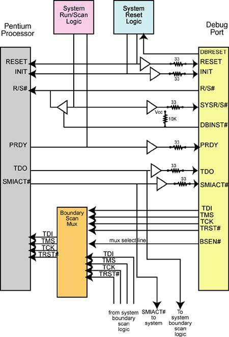
When the engineer wished to access the processor's TAP controller, the debug tool set the R/S# and BSEN# (Boundary Scan Enable) lines low. Setting the R/S# signal low caused the processor to freeze on the next instruction boundary. The PRDY (Probe Ready) signal was asserted by the processor to inform the debug tool that it had stopped execution. Asserting boundary scan enable (BSEN#) selected the boundary scan mux's “A” set of inputs to be gated to the processor's boundary scan TAP inputs. The tool could then access the processor's TAP controller to access the processor's debug registers and set up one or more breakpoints. In order to prevent the program from accessing the debug registers after they'd been set up by the debug tool, the GD bit would be set in the Debug Command register, DR7.
After the breakpoint(s) was set and the engineer wished to let the processor resume normal operation, the tool deasserted BSEN# and set R/S# high. The high on R/S# removed the processor from boundary scan mode and the deassertion of BSEN# disconnected the tool's boundary scan outputs from the processor and gates the system board's boundary scan signals to the processor's boundary scan inputs.
When in Probe Mode, the debug tool could use the boundary scan interface to access the processor's debug status register, DR6, to ascertain which breakpoint was detected (see the description of the DR6[BD] bit in the next sentence) and then display a visual indication to the engineer. DR6[BD] = 1 when DR7[GD] = 1 and the processor detects an attempt to access one of the debug registers. This protects the debug registers from being altered by the program while they are in use by an ICE or a debug tool. Through the TAP, the engineer could access and display any of the processor's internal registers.
The debug tool could monitor the processor's SMIACT# output to determine when the processor was in System Management Mode (SMM).