
The μop Pipeline's Major Elements
The Allocator
General
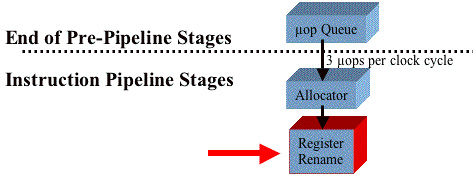
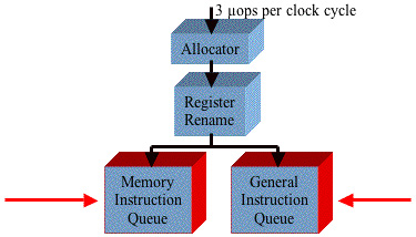
The Allocator was introduced in “The Allocator Stage” on page 931. Refer to Figure 38-37 on page 939. In the Allocator stage, for each of the three in-order μops the following core resources are allocated (i.e., reserved to be used by the three μops as they pass through the pipeline):
One of the 126 Reorder Buffer (ROB) entries is reserved to track the μop's completion status.
One of the 128 integer Register File (RF) entries or FP RF entries is reserved to hold the result data that will be produced by the μop when it is executed.
If the instruction is a load or a store, one of the 48 load or 24 store buffer entries is reserved to handle the load or store when it is executed.
An entry is reserved for the μop in either the Memory or the General μop Queue (a subsequent stage of the pipeline).

If any of the resources required by any of the three μops are not currently available (e.g., if all of the Register File entries are currently in use), the Allocator stalls this part of the machine. When those resource(s) become available, the Allocator assigns them to the starved μops and permits the three μops to proceed to the next pipeline stage (the Register Rename stage).
The ReOrder Buffer (ROB) Entry
Refer to Figure 38-38 on page 940. The processor core implements a 126-entry ROB. It is a circular buffer and the three μops are assigned the next three available entries in the ROB. Those three entries serve only one purpose: they track the status of the three μops as they proceed through the pipeline towards execution and completion. The status in each ROB entry contains the following information:
The status of the μop.
The number of the physical register in the integer or FP Register File that the result of the μop's execution will be deposited in.
The GPR or FP register that the result register represents.

This information is used in the Retirement stage.
As the μops proceed through the subsequent pipeline stages, the ROB entry number assigned to each of them assigned travels with them (as a tag). As a μop is processed in each stage, its status is updated in its assigned ROB entry. When the three μops complete execution and are retired, the three ROB entries become available to track the status of three more μops.
The Register File Allocation
As mentioned earlier, in the Register Rename stage any of a μop's three fields that references a processor's GPR (e.g., EAX, EBX, etc.) is tagged to point to a register in the integer or FP Register File. It should be obvious that if either of the source operands or the destination operand is a memory location, that field in the μop is not tagged to point to one of the registers in the Register File.
The tagging of the three μops does not actually occur until the Register Rename stage, but, in the Allocator stage, a register is reserved in either the integer or the FP Register file to hold the result of each μop's execution.
The Load and Store Buffer Allocation
If any of the three μops are loads or stores, the Allocator reserves an entry in one of the 48 Load Buffers or the 24 Store Buffers to handle the load or store when it is executed.
The Memory or General μop Queue Allocation
Refer to “The Memory and General μop Queues” on page 950.
The Register Rename Unit
General
The Register Rename stage was introduced in “The Register Rename Stage” on page 931. Refer to Figure 38-39 on page 941.
Figure 38-39. The Register Rename Unit
In the Register Rename stage, if either or both of a μop's two source operand fields references a GPR (e.g., EAX, EBX, etc.) or a FP data register, that field is tagged to point to the register in the integer or FP Register File that, when the μop ultimately arrives at the execution stage, will contain the required source value. It should be obvious that if either of the source operands is a memory location, that field in the μop is not tagged to point to one of the registers in the Register File.
In the Register Rename stage, register renaming is performed on the next three μops in strict program order simultaneously.
Renaming the Destination Register
The processor implements 128 integer data registers and 128 FP data registers (see Figure 38-40 on page 942). In the Allocator stage (the previous stage of the pipeline), up to three registers in the integer or the FP Register file were reserved to hold the results of each of the three μop's execution (note that if the destination is a memory location, no register need be reserved to hold the results of the μop's execution; rather, a Store Buffer is reserved to hold the store operation). In the Register Rename stage the destination fields in each of the three μops wherein the destination is a register are tagged to point to the physical register in which the μop's result will be written when the μop is ultimately executed.

Renaming the Source Register(s)
The Register Rename stage contains two Register Alias Tables, or RATs (see Figure 38-41 on page 944):
The integer Register File's RAT keeps a record of which registers in the integer Register File are the latest copies of each of the GPRs.
The FP Register File's RAT (not shown) keeps a record of which registers in the FP Register File are the latest copies of each of the FP data registers.
The seven items that follow describe how the Register Rename logic deals with each of the seven instructions shown in the illustration.
Refer to Figure 38-41 on page 944. When it is ultimately executed later in the pipeline, the first instruction (MOV EDX, MEM1) will read a value from a memory location into the EDX register. In the Register Rename Stage, the destination field in the μop is tagged so that when the μop is ultimately executed, its result (i.e., the data read from memory) will be placed in register 22 of the integer Register File. Register 22 was chosen because it is currently not in use. In other words, at this point in the program's execution, register 22 will be used as the EDX register. The Front-End Integer RAT records the fact that register 22 is the EDX register.
Refer to Figure 38-42 on page 945. When it is ultimately executed later in the pipeline, the second instruction (MOV EAX, MEM2) will read a value from a memory location into the EAX register. In the Register Rename Stage, the destination field in the μop is tagged so that when the μop is ultimately executed, its result (i.e., the data read from memory) will be placed in register 3 of the integer Register File. Register 3 was chosen because it is currently not in use. In other words, at this point in the program's execution, register 3 will be used as the EAX register. The Front-End Integer RAT records the fact that register 3 is the EAX register.
Refer to Figure 38-43 on page 946. When it is ultimately executed later in the pipeline, the third instruction (OR EDX, EAX) will perform a logical OR of the EAX and EDX registers and store the result in the EDX register. When this μop is dispatched for execution, register 3 will be used as the EAX register, register 22 as the EDX register, and the result of the OR operation will be stored in register 22. The RAT was consulted to determine the identities of the source registers, but the RAT is not updated.
Refer to Figure 38-44 on page 947. When it is ultimately executed later in the pipeline, the fourth instruction (MOV EAX, 12F7) will move the value 12F7h into the EAX register. In the Register Rename Stage, the destination field in the μop is tagged so that when the μop is ultimately executed, its result (i.e., the value 12F7h) will be placed in register 76 of the integer Register File. Register 76 was chosen because it is currently not in use. In other words, at this point in the program's execution, register 76 will be used as the EAX register. The Front-End Integer RAT records the fact that register 76 is the EAX register.
Refer to Figure 38-45 on page 948. When it is ultimately executed later in the pipeline, the fifth instruction (MOV EBX, MEM1) will read a value from a memory location into the EBX register. In the Register Rename Stage, the destination field in the μop is tagged so that, when the μop is ultimately executed, its result (i.e., the data read from memory) will be placed in register 103 of the integer Register File. Register 103 was chosen because it is currently not in use. In other words, at this point in the program's execution, register 103 will be used as the EBX register. The Front-End Integer RAT records the fact that register 103 is the EBX register.
Refer to Figure 38-46 on page 949. When it is ultimately executed later in the pipeline, the sixth instruction (SUB EBX, 5) will subtract the value 5 from the EBX register and store the result in the EBX register. When this instruction is dispatched for execution, register 103 will be used as the EBX register and the result of the subtract operation will be stored in register 103. The RAT is not updated. The RAT was consulted to determine the identity of the the EBX register, but the RAT is not updated.
Refer to Figure 38-47 on page 950. When it is ultimately executed later in the pipeline, the seventh instruction (ADD EAX, EBX) will add the EBX and EAX registers and store the result in the EAX register. When this instruction is dispatched for execution, register 76 will be used as the EAX register, register 103 as the EBX register, and the result of the OR operation will be stored in register 76. The RAT was consulted to determine the identities of the source registers and the destination register, but the RAT is not updated.


Renaming Eliminates False Register Dependencies
Refer to Figure 38-47 on page 950. The second and fourth instructions in the IA32 code fragment both moved values into the EAX register. Due to register renaming, however, the dependency that these two instructions had on the same destination register was eliminated. When these two μops arrive at the Dispatch stage, they can both be dispatched for execution simultaneously. The values are actually moved into separate physical registers in the integer register file (registers 3 and 76).
The Memory and General μop Queues
See Figure 38-48 on page 951. In the next clock cycle, the three μops that just underwent register renaming are forwarded into the two μop queues. Any loads or stores are pushed into the Memory μop Queue, and the remaining μops are pushed into the General μop Queue (also called the Integer/FP Queue).
Figure 38-48. The Memory and General μop Queues
Each of these queues stores the μops in strict FIFO (first-in, first-out) order with respect to the μops in the same queue, but each queue is allowed to be read (by the μop schedulers) out-of-order with respect to the other queue.
The Schedulers Enable Out-of-Order Execution
Refer to Figure 38-49 on page 953. The processor core implements four instruction schedulers:
The Memory Scheduler.
The Fast Scheduler.
The Slow/General FP Scheduler.
The Simple FP Scheduler.

Table 38-1 on page 952 defines the relationship of the Memory and General μop Queues, the schedulers, and the μop dispatch ports. The schedulers maintain their own instruction queues which are fed by the Memory and General μop Queues. The μops are placed in these two queues in strict program order and the schedulers pop them from each queue in strict order (relative to the instructions in that queue). Each queue, however, can be read out-of-order with respect to the other queue. The μops are placed in the queue associated with the appropriate scheduler (depending on the μop type). Each of the scheduler queues has between eight and twelve entries.
| Scheduler | Is Fed by | Supplies Dispatch Port |
|---|---|---|
| Memory Scheduler | Memory μop Queue |
|
| Fast Scheduler | General μop Queue |
|
| Slow/General FP Scheduler | General μop Queue |
|
| Simple FP Scheduler | General μop Queue |
|
Until the instructions are placed in the scheduler queues, all of the front-end pipeline and μop pipeline stages have dealt with the μops in strict program order. Once placed in the scheduler queues, however, the schedulers can dispatch any μop for execution when its input register operand(s) become available (i.e., they have been produced by the execution of instructions earlier in the program flow) and the execution resources it requires are available. As mentioned earlier, in some cases, a μop may be dispatched with the expectation that the execution of another μop may have produced the required input operand by the time the μop is executed. If, when the μop is executed, the operand has not yet become available, the μop is scheduled for a Replay (see Table 38-2 on page 962).
Stores are always executed in strict program order with reference to each other.
If multiple schedulers have μops ready to be issued through the same dispatch port (port 0 or 1), they arbitrate for use of the dispatch port (the arbitration scheme is not in the public domain).
The Register Files Are Strategically Placed
Refer to Figure 38-50 on page 954. The integer and FP Register Files are located between the schedulers and the execution units to permit fast access to source operands that must accompany an μop, as well as fast update of the destination register with the result of an μop's execution. In addition, each of the Register Files implements a multi-clock bypass network that forwards the result of an executed μop (which has not yet been written into the register file) to any μops in the scheduler queues that require the result as one of its source operands.

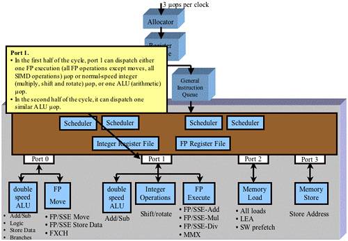
Dispatch Port 0
Refer to Figure 38-51 on page 955. Port 0 is attached to the following execution units:
One of the double-speed ALUs. This unit is capable of executing two of the following operations per clock cycle:
- An integer add or subtract μop.
- A logical μop.
- A Store Data μop for an integer store operation. Note that an IA32 store instruction decodes into two μops which must be executed simultaneously by the Store Address (on Port 3) and Store Data execution units (on Port 0 or Port 1). When executed, the Store Address μop generates the start memory address to which the data will be written, while the Store Data μop generates the data to be written.
- A branch μop.
The simple FP Move execution unit. This unit is capable of executing one of the following operations per clock cycle:
- A FP or SSE Move μop.
- A FP or SSE Store Data μop.
- A FP exchange μop.
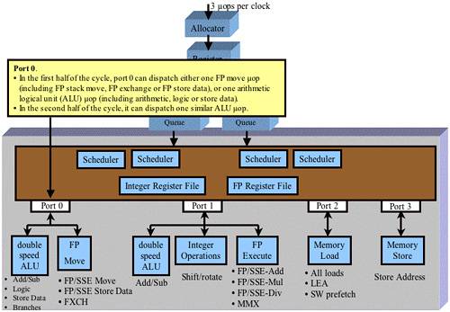
Dispatch Port 1
Refer to Figure 38-52 on page 956. Port 1 is attached to the following execution units:
The other double-speed ALU. Unlike the double-speed ALU attached to Port 0, this one can only execute integer add and subtract μops.
The Integer Operations unit executes shift and rotate μops.
The Complex FP execution unit. It executes:
- FP or SSE add μops.
- FP or SSE multiply μops.
- FP or SSE divide μops.
- MMX μops.
The Complex FP execution unit actually consists of the execution units listed in Figure 38-53 on page 957.

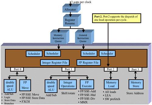
Dispatch Port 2
Refer to Figure 38-54 on page 958. Port 2 is only attached to the Memory Load execution unit. This unit executes:
All load μops.
The LEA (Load Effective Address) μop.
The prefetch μop.
Dispatch Port 3
Refer to Figure 38-55 on page 959. Port 3 is only attached to the Memory Store Address execution unit. As mentioned earlier, an IA32 store instruction decodes into two μops which must be executed simultaneously by the Store Address and Store Data execution units. When executed, the Store Address μop generates the start memory address to which the data will be written, while the Store Data μop generates the data to be written.

Instruction Dispatch Rate
The number of μops that may be issued through the four ports in a given clock cycle ranges from a low of zero to a high of six. The maximum issue rate is achieved under the following circumstances:
Two simple integer μops are issued through Port 0 to the double-speed ALU.
Two simple integer μops are issued through Port 1 to the double-speed ALU.
One μop is issued through Port 2.
One μop is issued through Port 3.
The Complex Execution Units Are Pipelined
A number of the μops handled by the more complex execution units take more than one clock cycle to execute. Each of the complex execution units contains its own instruction pipeline through which each instruction passes from dispatch to completion. As an example:
In clock 1, the execution unit accepts a new μop from the dispatch port.
In clock 2, that μop is shifted to the next stage of the pipeline and a new μop is accepted into the first pipeline stage from the dispatch port.
Most of the execution units can start executing a new μop every cycle (either because they are pipelined or because an instruction can complete execution in one clock cycle. The double-speed ALUs can execute many of the simple integer instructions at the rate of two per clock cycle. The FP execution unit can accept a new instruction every two cycles.
The Retirement Stage
General
The Retirement stage is not shown in Figure 38-55 on page 959.
If the following criteria have been met, the retirement logic retires the oldest three μops in each clock cycle:
All three μops have completed execution (as indicated by the status in their respective ROB entries).
All upstream conditional branches have completed execution and it has been established that these three μops should have been executed.
Refer to Figure 38-56 on page 961. The Retirement RATs (the Retirement Integer RAT and the Retirement FP RAT; note that only the integer RAT is shown in the figure) keeps track of the latest version of each of the GPRs and the FP data registers. These are the alias registers that represent the processor's IA32 data registers at any given moment in time.
Figure 38-56. The Retirement RAT

The status in each ROB entry contains the following information:
The status of the μop.
The number of the physical register in the integer or FP Register File that the result of the μop's execution will be deposited in.
The GPR or FP register that the result alias register represents.
This information is used in the Retirement stage.
As each μop is completed, it is marked Ready-for-Retirement in its respective entry in the ROB. The retirement logic waits until the oldest three μops in the ROB have been completed and then retires them in a single clock cycle. During the clock when the oldest three μops are retired, using each of the three ROB entries' result register number and associated GPR or FP register, the retirement RAT is updated to point to the latest copy of the GPRs or FP registers.
μop Retirement vs. IA32 Instruction Retirement
As mentioned at the beginning of this chapter, each IA32 instruction is decoded into one or more μops. The results of an IA32 instruction's execution must not alter the processor's register set (i.e., the registers that are visible to the programmer; not the alias registers) until ALL of the μops that comprise the IA32 instruction have completed execution. This highlights the fact that the final (or only) μop that represents the IA32 instruction is tagged as the final μop. When the retirement logic retires the final (or only) μop associated with an IA32 instruction, that is when the alias registers that are currently playing the role of the processor's data registers are made visible to the programmer.