
Intro to the μop Pipeline
General
While the μop pipeline in the P6 processors consisted of 10 stages, the Pentium® 4 pipeline was completely re-designed and expanded to 20 stages (see Figure 38-22 on page 929). Intel® refers to this as a hyper-pipelined design. The operational processor core clock rate determines how many gates of logic can be included in each pipeline stage. Dividing the core's pipeline into less complex stages with less work performed in each stage (with fewer logic gates) permits a significantly higher core clock frequency.
While Intel® has provided the names of the pipeline stages, it should be stressed that, in public domain documentation, it does not provide a description of precisely what happens in each stage. The sections that follow represent the author's attempt at hopefully “intelligent” speculation.
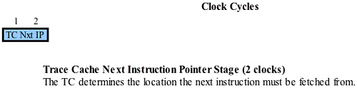
The TC Next IP Stage
Refer to Figure 38-23 on page 929. The first stage of the instruction pipeline is the TC Nxt IP stage and it takes two clock cycles to complete. Using the current CS:EIP pointer, a lookup is performed in the Trace Cache to determine if the next three μops of the currently-executing program are in the cache.
The TC Fetch Stage
Refer to Figure 38-24 on page 930. The next stage of the μop pipeline is the TC Fetch stage and it takes two clock cycles to complete.
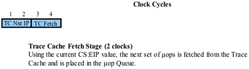
Assuming that the TC Nxt IP stage resulted in a Trace Cache hit, the next 3 μops in strict program order are read from the cache and loaded into the μop Queue.
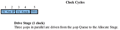
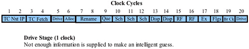
The Drive 1 Stage
Refer to Figure 38-25 on page 930. The next stage of the μop pipeline is the Drive stage and it takes one clock cycle to complete. The three μops in the μop Queue are driven to the Allocator stage.
The Allocator Stage
Refer to Figure 38-26 on page 931. The next stage of the μop pipeline is the Allocator stage and it takes one clock cycle to complete.
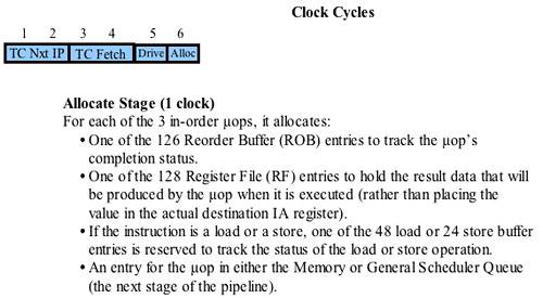
For each of the three in-order μops, the following core resources are allocated (i.e., reserved to be used by the three μops as they pass through the pipeline):
One of the 126 Reorder Buffer (ROB) entries is reserved to track the μop's completion status.
One of the 128 integer Register File (RF) entries or FP RF entries is reserved to hold the result data that will be produced by the μop when it is executed.
If the instruction is a load or a store, one of the 48 load or 24 store buffer entries is reserved to handle the load or store when it is executed.
An entry is reserved for the μop in either the Memory or the General μop Queue (a subsequent stage of the pipeline).
A detailed description of the Allocator stage can be found in “The Allocator” on page 938.
The Register Rename Stage
Refer to Figure 38-27 on page 932. The next stage of the μop pipeline is the Register Rename stage and it takes two clock cycles to complete.
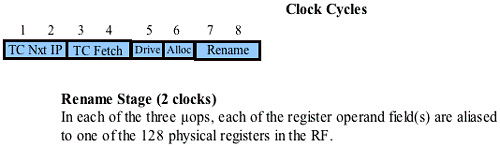
Most IA32 instructions reference one or two source operands and a destination operand. In the following example:
add eax,ebx ;add eax and ebx and store result in eax
the EAX and EBX registers are the source operands and the EAX register is the destination operand. In order to execute this instruction, the processor must read the contents of the EAX and EBX registers, perform the add, and write the result into the EAX register.
Earlier, in the front-end pipeline Decoder stage, the IA32 instruction was decoded into one or more equivalent μops. Intel® refers to the μops as triadic μops because each μop contains three fields that specify two source operands and one destination operand. In the Register Rename stage, any of a μop's three fields that reference one of the processor's GPRs (e.g., eax, ebx, etc.; see Figure 38-28 on page 932) is tagged to point to a register in the integer or FP Register File. It should be obvious that if either of the source operands or the destination operand is a memory location, that field in the μop is not tagged to point to one of the registers in the Register File.
Figure 38-28. The GPRs
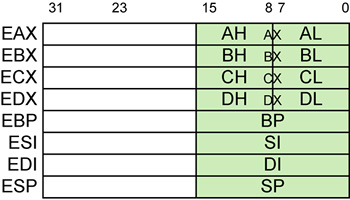
In the Register Rename stage, register renaming is performed on the three μops simultaneously.
A detailed description of the Register Rename stage can be found in “The Register Rename Unit” on page 941.
The Memory and General μop Queue Stage
Refer to Figure 38-29 on page 933. The next stage of the μop pipeline is the Queue stage and it takes one clock cycle to complete.
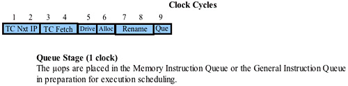
The three μops that just underwent register renaming are forwarded into one of two queues:
All load and store μops are forwarded into the Memory μop Queue.
All other μops are forwarded into the General μop Queue.
Each of these queues stores the μops in strict FIFO (first-in, first-out) order with respect to the μops in the same queue, but each queue is allowed to be read (by the μop schedulers) out-of-order with respect to the other queue.
More information on this stage can be found in “The Memory and General μop Queues” on page 950.
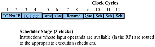
The Scheduler Stage
Refer to Figure 38-30 on page 934. The next stage of the μop pipeline is the Scheduler stage and it takes three clock cycles to complete.
There are several μop schedulers. As space becomes available in a scheduler queue, it pops μops from the General μop Queue or the Memory μop queue and places them in its own scheduler queue. The scheduler then determines when a μop is ready to execute based on:
the availability of its dependent input register operand sources and
the availability of execution unit(s) necessary to execute the instruction.
When these conditions are met, the μop can be dispatched to the appropriate execution unit. In some cases, a μop may be dispatched with the expectation that the execution of another μop may have produced the required input operand by the time the μop is executed. If, when the μop is executed, the operand has not yet become available, the μop is scheduled for a Replay (see Table 38-2 on page 962).
| Term | Description |
|---|---|
| Replay | To achieve the optimum performance when dealing with commonly-encountered cases, the scheduler sometimes schedules μops for execution before all of the conditions for correct execution are guaranteed to be satisfied. Obviously, the hope is that, by the time the instruction is actually dispatched for execution, the condition(s) will have been met.
If they have not, the μop must be re-issued and this is referred to as Replay. Some causes of Replays are:
|
| Assist | Under some circumstances, the processor's hardware needs the assistance of microcode to deal with an event. This is referred to as an Assist. A classic example is an underflow condition caused by a FP operation's input operands. The hardware must modify the format of the operands before it can perform the computation. If a program causes the processor to take too many Assists, this can have a drastic effect on performance because all μops are cleared from the processor's entire instruction pipeline when each Assist is taken. |
| Bogus instruction | When a branch misprediction occurs, all of the μops in the instruction pipeline, as well as the IA32 instructions in the front-end pipeline stages have to be flushed. Those IA32 instructions and μops are referred to as bogus instructions and bogus μops. A number of Pentium® 4 processor performance monitoring events, for example, instruction_ retired and μops_retired, can count instructions or μops that are retired on the characterization of bogus versus non-bogus. |
| Non-bogus instruction | Instructions that do not get flushed due to a branch misprediction are referred to as retired or as non-bogus instructions. |
| Tagging | Tagging is related to the Performance Counters. It is a means of marking μops to be counted at retirement. The tagging mechanisms allow a μop to be tagged once during its lifetime in the pipeline. |
| Partial stall | If a full register (EAX, EBX, ECX, or EDX) is read (e.g., MOV EBX, EAX) after part of the register is written to (e.g., MOV AL, 5), the processor experiences a multi-clock stall. The μop that reads from the full register is stalled until the partial write is retired, writing the data to the subset of the destination GPR. Only then is the 32-bit value read from the full GPR. In addition, none of the μops that follow the full register read μop will be executed until the full register read completes. Since 16-bit code performs partial-register writes a lot, the processor suffers poor performance when executing 16-bit code. |
Additional information on the schedulers can be found in “The Schedulers Enable Out-of-Order Execution” on page 951.
The μop Dispatch Stage
Refer to Figure 38-31 on page 935. The next stage of the μop pipeline is the Dispatch stage and it takes two clock cycles to complete.

In this stage, the schedulers dispatch μops that are ready for execution and the required execution units are available.
Additional information on the Dispatch stage can be found in the following sections:
“Dispatch Port 0” on page 954.
“Dispatch Port 1” on page 956
“Dispatch Port 2” on page 957
“Dispatch Port 3” on page 958
“Instruction Dispatch Rate” on page 959
The Register File Stage
Refer to Figure 38-32 on page 935. The next stage of the μop pipeline is the Register File stage and it takes two clock cycles to complete.
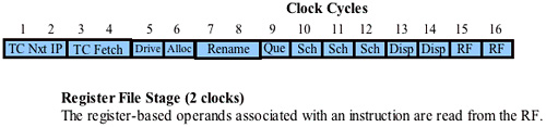
In this stage, any source operands (i.e., register contents) required for the μop's execution are read from the integer or the FP register file.
The Execution Stage
Refer to Figure 38-33 on page 936. The next stage of the μop pipeline is the Execution stage and it takes one clock cycle to complete.
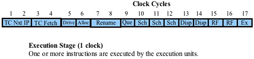
In this stage, one or more μops are executed by the execution units.
The Flags Stage
Refer to Figure 38-34 on page 936. The next stage of the μop pipeline is the Flags stage and it takes one clock cycle to complete.
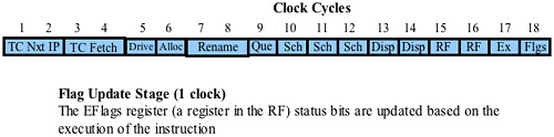
In this stage, status bits are set or cleared in the appropriate processor status registers (i.e., the EFlags register, the FSW register, the MXCSR register, etc.) based on the execution of the μops.
The Branch Check Stage
Refer to Figure 38-35 on page 937. The next stage of the μop pipeline is the Br Ck stage and it takes one clock cycle to complete.
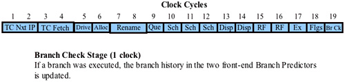
This name (Br Ck) is open to interpretation and the author thinks it stands for Branch Check. If a conditional branch was executed, the branch history in the two front-end BTBs is updated. In addition, if it turns out that the branch prediction for the branch was mispredicted, then the μops that followed the conditional branch through the pipeline were fetched from the wrong path. In that case, all of those μops must be deleted from the pipeline and, if any of them had been speculatively executed before the conditional branch was executed, the results of their execution is also deleted. Finally, the Br CK stage must signal to the CS:EIP logic to start fetching instructions from the correct path. Optimally, those μops will be sourced from the Trace cache, but if they are not in the Trace Cache they must be fetched from the L2 Cache, the L3 Cache (if the processor implements one), or from system memory over the FSB.
The Drive 2 Stage
Refer to Figure 38-36 on page 937. The next stage of the μop pipeline is the Drive stage and it takes one clock cycle to complete.
There is not enough information supplied to make an intelligent guess as to what's being driven to whom.