
Interrupt Messages
Introduction
Interrupt messages can be categorized as follows:
Inter-Processor Messages sent from the Local APIC of one processor to the Local APIC of one or more other processors, or sent by a Local APIC to itself. The following are inter-processor messages:
- On a system incorporating multiple P6 family processors on the FSB, the processors exchange a series of BIPI and FIPI messages at startup time to determine which of them will be the Boot Strap processor (BSP). See chapter 4 of the MindShare book entitled Pentium® Pro and Pentium® II System Architecture, Second Edition for more information. These messages were eliminated in the Pentium® 4 processor family.
- The Startup Inter Processor Interrupt (SIPI) message. This message is sent to the APs (Application Processors) in a multiprocessor system during the boot process. It commands each of them to execute an initialization program that has been placed in memory by the BSP. See “How the APs are Discovered and Configured” on page 888 for more information.
- The OS Sends a Task Dispatch Message. Once the OS has been booted, the OS scheduler assigns a task to a processor by placing the task in memory and issuing a user-defined interrupt to the target processor's Local APIC. Upon message receipt, the target processor executes the user-defined interrupt handler, causing it to begin execution of the task.
- One Processor Forwards an Interrupt to Another Processor. A processor's Local APIC may receive an interrupt and dispatch it to its processor core. The target interrupt handler may decide to pass the interrupt to another processor for servicing by causing the Local APIC to forward the interrupt in an interrupt message to another processor's Local APIC.
Interrupt Messages Originated by Device Adapters. A device adapter that requires servicing may generate an interrupt by:
- Asserting an IRQ signal to the IO APIC module in the chipset. Upon detection of the IRQ, the IO APIC formulates an interrupt message and sends it to one or more processors for handling.
- Generating a Message Signaled Interrupt (MSI). The MSI takes the form of a memory write. Assuming that the system is based upon a Pentium® 4 family processor, the chipset receives the memory-mapped IO write (i.e., the MSI) and forwards the memory write to the processor FSB. This interrupt message targets one or more processors to handle the interrupt.
Interrupt Messages Originated by the Chipset. Under platform design-specific circumstances, the chipset may send one of the following types of interrupt messages to one or more of the processors to be handled:
- SMI.
- INIT.
- NMI.
Sending a Message From the Local APIC
The software executing on a processor causes the processor's Local APIC to send a message by writing to the Local APIC's Interrupt Command Register (ICR; see Figure 61-25 on page 1557). The bit fields in the ICR are described in Table 61-6 on page 1558.
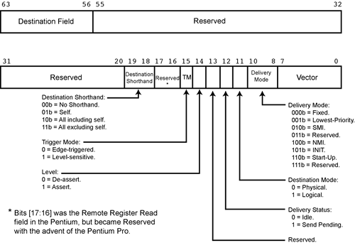
| Bit Field | Field Width in bits | Description |
|---|---|---|
| Destination Field | 8 | Specifies the target processor or processors. This field is only used when no Destination Shorthand is used (see the next row in this table):
|
| Destination Shorthand | 2 | A Destination Shorthand can be used in place of the 8-bit Destination field and software can send a shorthand message by performing a single 32-bit memory write to the low half of the ICR. The following Shorthands are defined:
|
| Trigger Mode | 1 | When using the INIT Level De-assert Delivery Mode, this bit selects the Trigger Mode:
|
| Level | 1 | For the INIT Level De-assert Delivery Mode, this bit must be set to 0. For all other Delivery Modes it must be set to 1. This bit has no meaning in Pentium® 4 family processors and is always 1. |
| Delivery Status | 1 |
|
| Destination Mode | 1 | Selects either:
|
| Delivery Mode | 3 | Also referred to as the IPI Message Type field. Specifies the type of IPI message to be sent:
|
| Vector | 8 | If the Delivery Mode is set to Fixed, this field contains the 8-bit user-defined interrupt vector to be delivered to the target processor or processors. |
To transmit most types of interrupt messages, the programmer must perform two memory writes:
The first write is to the upper half of the ICR to set the Destination field.
The second write is to the lower half of the ICR. This write provides the remaining information related to the message and triggers the Local APIC to transmit the message defined by the ICR content.
If a message is to be transmitted only to the source Local APIC (i.e., a loopback operation), to all Local APICs except the source Local APIC, or to all Local APICs including the source Local APIC, the programmer need only perform one memory write to the lower half of the ICR. The Destination Shorthand field must be set to a value other than 00b.
Physical Destination Mode
When the ICR Destination Mode field is set to Physical Destination Mode, the interrupt message is accepted only by the processor whose Local APIC has a match on the APIC ID specified in the ICR's Destination field.
Logical Destination Mode
Introduction
When the ICR Destination Mode field is set to Logical Destination Mode, the interrupt message is accepted by all of the processors whose Local APICs belong to the targeted group.
In Logical Destination Mode, the interrupt message destination is specified by the ICR's 8-bit Destination field value (referred to as the Message Destination Address, or MDA). Upon receipt of a message specifying Logical Destination Mode, a Local APIC compares the message's MDA with the values in its Logical Destination Register (LDR; see Figure 61-26 on page 1564) and Destination Format Register (DFR; see Figure 61-27 on page 1564) to determine if it should accept and handle the interrupt. The Logical APIC ID in the LDR (Figure 61-26 on page 1564) must not be confused with the Local APIC ID in the Local APIC ID register (see Figure 61-12 on page 1514).
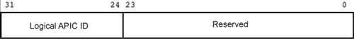
Figure 61-27. Destination Format Register (DFR)

The DFR's Model field (see Figure 61-27 on page 1564) selects one of two models and when a message is received and specifies Logical Destination Mode, is used to interpret the message's MDA (in the Destination field). The interpretation of the MDA value for the two models is described in the following paragraphs.
The Flat Model
In the Flat Model, each of the eight bits in the message's Destination field acts as an selector bit permitting the message to select up to 8 Local APICs by setting the appropriate bits to one in the MDA. In each of the Local APICs, the Logical APIC ID field in each of their respective LDRs is programmed as follows (the references to Local APIC 0, Local APIC 1, etc. refers to a Local APIC's ID number within the logical group):
00000001b is stored in Local APIC 0's Logical APIC ID field.
00000010b is stored in Local APIC 1's Logical APIC ID field.
00000100b is stored in Local APIC 2's Logical APIC ID field.
00001000b is stored in Local APIC 3's Logical APIC ID field.
00010000b is stored in Local APIC 4's Logical APIC ID field.
00100000b is stored in Local APIC 5's Logical APIC ID field.
01000000b is stored in Local APIC 6's Logical APIC ID field.
10000000b is stored in Local APIC 7's Logical APIC ID field.
In the following example, the message sender is transmitting the message to 5 of the 8 processors in the logical group:
 10110011b  MDA field selects Local APICs 0, 1, 4, 5 and 7
 00100000b
								Contents of Local APIC 5's LDR
 00100000b  Local APIC 5 receives the message, ANDs
            the MDA and its Local APIC ID, yielding
            a non-zero result, so   APIC 5 is a member of
            the targeted group
The Cluster Model
This model supports two basic destination schemes:
Flat Cluster. This scheme is not supported on the Pentium® 4 processor family.
Hierarchical Cluster.
The Flat Cluster Model
Using this model, all of the Local APICs are assumed to be connected through the 3-wire APIC bus. The high-order four bits of the message's MDA (bits [31:28] of the ICR's Destination field) contains the target Cluster ID (1-of-15; the valid cluster IDs are 0h through Eh), while the lower four bits (bits [27:24] of the ICR's Destination field) are used as select bits to select up to four Local APICs within the cluster as targets of the message.
Upon message receipt, a potential target Local APIC compares bits [31:28] of the message's MDA field with bits [31:28] of its LDR to determine if it's part of the target logical cluster. Assuming it is, the Local APIC ANDs bits [27:24] of the message's MDA field with bits [27:24] of its LDR and, if the result is non-zero, the Local APIC accepts the message.
The Pentium® and P6 APIC bus arbitration mechanism only supports a maximum of 15 APIC agents, however, so the total number of processors supported in this mode is limited to 15. Broadcast to all local APICs is achieved by setting all of the bits in the ICR's Destination field to one. This guarantees a match on all clusters, and selects all APICs in each cluster.
The Hierarchical Cluster Model
This cluster model can be used with the Pentium® 4 family, the P6 family, or Pentium® processors. A hierarchical network can be created by including a Cluster Routing device on each FSB (for the Pentium® 4 family), or each APIC bus (for the P6 or Pentium® families). The Cluster Routing device uses the target cluster ID in an interrupt message to route the message to the target cluster's FSB or APIC bus. The Cluster Routing device is not an off-the-shelf Intel® part. Rather, it is system design-specific.
Lowest-Priority Delivery Mode
General
When this Delivery Mode is specified in a message, the message also specifies one of the following:
Logical Destination Mode.
“All Including Self” destination shorthand.
“All Excluding Self” destination shorthand.
The group of Local APICs that are targeted by the message then all arbitrate for ownership of the FSB (for the Pentium® 4 family), or the APIC bus (for the P6 or Pentium® families):
On the Pentium® 4 processor family, the group of targeted processors then exchange interrupt messages in order to determine which of them is currently executing the lowest-priority program (as specified in their respective TPRs).
On the Pentium® and P6 family processors, the Local APICs within each processor compare their TPR values bit-by-bit over the 3-wire APIC bus to determine which of them is currently executing the lowest-priority program.
The processor that is executing the lowest-priority program then accepts the original interrupt message and is interrupted.
This mode of operation is not recommended for the Pentium® 4 processor family because the resulting multiple interrupt messages consume FSB bandwidth and therefore can degrade system performance. This is not a problem on the P6 or the Pentium® processor families because the interrupt messages are transmitted over the 3-wire APIC bus and do not consume any FSB bandwidth.
Chipset-Assisted Lowest-Priority Delivery
As mentioned in the previous section, use of the Lowest-Priority Delivery Mode is not recommended for the Pentium® 4 processor family. This section describes an alternative implementation of this mode, but it only applies to user-defined interrupts being delivered to the processors by the chipset (it does not apply to NMI, INIT, or SMI).
Assume that a device adapter asserts an IRQ signal to request service from the interrupt handler within its device driver.
The IRQ is received on one of the inputs of the IO APIC within the chipset.
The IO APIC consults the Redirection Table entry associated with the respective IRQ line and determines that this IRQ is to be sent to the processor that is currently executing the lowest-priority (and therefore the most interruptible) program.
The chipset consults a set of memory-mapped IO registers (within the chipset). Each one of these registers is associated with a processor. Whenever the OS writes a new value into a Local APIC's TPR, the OS also performs a memory-mapped IO write to the chipset register associated with that processor. In this way, the chipset is aware of the priority of the programs being executed on the various processors.
After consulting the chipset-specific, memory-mapped IO register set, the chipset arbitrates for ownership of the FSB and initiates an interrupt message transaction directing the device adapter's interrupt to the processor executing the lowest-priority program. It uses Physical Destination Mode in the message.
It must be stressed that it is chipset-specific whether or not this method is supported. Also, the memory-mapped IO addresses at which the registers are implemented is chipset-specific. The OS must be aware of the chipset's support and must know the chipset memory-mapped IO port addresses to which the task priority for each processor must be written.
Alternatively, the device adapter may generate an interrupt by performing an MSI memory write [see “Message Signaled Interrupts (MSI)” on page 1584] rather than by asserting an IRQ signal. In this case, the message delivered to the chipset by the MSI memory write may specify Lowest-Priority Delivery Mode. If it does, the chipset performs steps 3 and 4 to select the target processor and deliver the interrupt to it. Additional information can be found in “Direct-Delivery of the MSI” on page 1586.
Just as a note of interest, in Intel®'s Itanium processor documentation, the optional, chipset-specific memory-mapped IO ports into which the OS writes the task priority for each processor are referred to as the XTP (External Task Priority) registers.